Solved cycle diagram of a regenerative gas turbine Brayton pv turbine power cycles thermodynamics volume 10 ideal diesel cycle a on pv diagram, b on ts diagram; the cycle
[DIAGRAM] Steam Power Plant Ts Diagram - MYDIAGRAM.ONLINE
Working of gas turbine cycle with regenerator Brayton cycle [diagram] steam power plant ts diagram
Diesel, gas turbine and combined cycle power plants
Solved draw a t-s diagram of the gas power cycle, which isSolved problem 3: a regenerator is added to the schematic Solved an ideal regenerative gas turbine power cycle isT-s diagram for open gas turbine cycle figure 4 shows a temperature (t.
B. t-s diagram of an open type gas turbine cycleDraw ts diagrams for the following ideal gas cycles: a) otto b) diesel T engine diagramWhat is diesel cycle? process, derivation, diagram & efficiency.
T-s diagram of the proposed combined cycle; (a) t-s diagram of the gas
Diesel cycle diagram pv ts process efficiency pdf definition derivation application notes[pdf] thermal analysis of open-cycle regenerator gas-turbine power #03 t s diagram for regenerative gas turbine with intercooling and18 rankine cycle report.
Regenerative cycle and its advantages & disadvantagesPv and ts diagram of stirling engine cycle. T-s diagram for triple-pressure hrsg of ccgt什么是奥托循环- p-v和t-s图最简单的解释?——新利18app官网备用机械增压.

Consider a combined gas-steam power cycle. the topping cycle is a
T-s diagram of the combined power cycle showing the relevantSample gas turbine cycle and (t-s) diagram[1] 2: t-s diagram of ideal brayton cycle.T-s diagram of the combined cycle gas turbine ccgt process.
Diesel cycle: definition, process, pv and ts diagram, derivationSolved figure 1 and figure 2 show the schematic diagrams for Otto cycleConsider a combined gas-steam water power plant that has a net power.

[diagram] gas turbine pv diagram
.
.


T-S diagram for triple-pressure HRSG of CCGT | Download Scientific Diagram

Draw ts diagrams for the following ideal gas cycles: a) otto b) diesel

#03 T S diagram for regenerative gas turbine with intercooling and

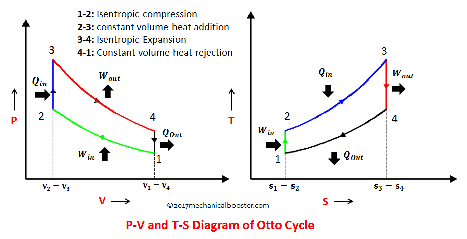
Otto Cycle - Definition, PV Diagram and TS Diagram
![[DIAGRAM] Steam Power Plant Ts Diagram - MYDIAGRAM.ONLINE](https://i2.wp.com/d2vlcm61l7u1fs.cloudfront.net/media/ca9/ca9342a2-fa6c-4ec4-9049-7ec11f49788b/php46EzSo.png)
[DIAGRAM] Steam Power Plant Ts Diagram - MYDIAGRAM.ONLINE

Diesel Cycle: Definition, Process, PV and TS Diagram, Derivation

10 Ideal Diesel cycle a on PV diagram, b on TS diagram; the cycle
![[PDF] Thermal Analysis of Open-Cycle Regenerator Gas-Turbine Power](https://i2.wp.com/d3i71xaburhd42.cloudfront.net/e198c9d3f6e550e88ae80161a625649c516e50a7/3-Figure2-1.png)
[PDF] Thermal Analysis of Open-Cycle Regenerator Gas-Turbine Power